
Cutting Map: What It Is and How to Get It Right
The drawing your order is cut from. What it has to show, how to build one online, and how to hand it over so that no part comes back 3 mm short.
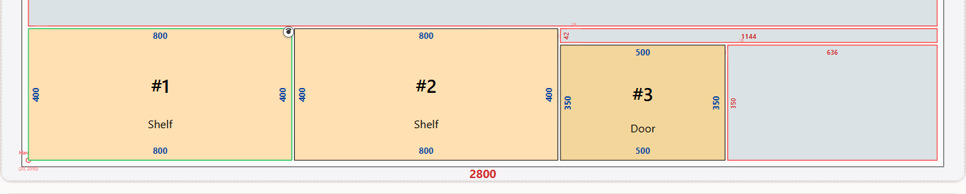
A cutting map is a diagram of a sheet with your parts placed on it: what sits where, how each part is rotated, and which lines the saw will follow. It is the working document of the cutting shop — the machine follows it, and so does whoever checks the finished order.
A mistake here costs more than a mistake in a drawing. A drawing can be corrected before the material is ordered; a cutting map cannot, because by then the sheet is already cut. So it is worth taking apart piece by piece.
What a cutting map must show
The minimum set, without which the map will not be accepted for work.
- Sheet size and material. Format, thickness, board type and colour. Without them it is unclear what to cut from.
- Part outlines with dimensions. Each part labelled with length, width and a number. The number matters for parts that share dimensions but differ in edge banding.
- Cut lines. The cutting order, not just the borders between parts. On a guillotine saw every cut runs right through the sheet, and the layout has to respect that.
- Edge banding marks. Which sides get banding and how thick. Banding changes the final dimension, so the shop needs to see it on the diagram.
- Drilling and groove marks. Holes for hinges and confirmat screws, if they are machined on the same equipment.
- Remnants and waste. What will be left of the sheet — so that the usable pieces come home with you instead of staying in the shop.
On the canvas each of these layers toggles separately: Dimensions, Edges, Drillings, plus a switch between the colour and black-and-white view. Black and white prints better; colour makes it easier to tell materials apart on screen.

How to make a cutting map online
The map is not drawn by hand — it comes out of the calculation. Your job is to describe the inputs precisely.
3 mm of kerf and 10 mm of edge margin by default. These are the two values people most often forget to check, and they shift every boundary on the map.
Sheets are the material you will buy; offcuts are what already sits in the workshop, with an explicit quantity.
Quick entry through length, width, quantity and name — or import an existing list from Excel.
Banding can be set while entering a part by ticking the sides. "Auto" rotation lets the part turn; "Length" and "Width" lock the grain direction.
Along the length, along the width, or — on the Pro plan — Optimal (ILP) with a goal of minimum waste, minimum sheets or minimum cuts.
A line reading "48 / 50" means two parts did not fit. The usual cause is a part larger than the sheet once edge margins are applied.
For what goes into the calculation itself and how to pick a mode, see our breakdown of particleboard cutting calculation.
When the map needs adjusting by hand
The algorithm optimises area; it knows nothing about your production circumstances. That is why a finished cutting map can be reworked manually in the editor.
- Rotate a part to follow the grain. In "Auto" mode the algorithm will rotate a part for density without seeing the pattern on the board. On visible surfaces that shows.
- Group the order by sheet. If some parts are cut on a different day or in a different colour, move them between sheets through the buffer.
- Nudge a part to the edge. The magnet snaps a part to its neighbours and to the sheet boundary, so you do not leave useless two-millimetre gaps.
- Improve the shape of the remnant. Sometimes it is better to gather the free area into one rectangle than to leave it as strips along the edges.
Which format to send to production
There are four, and the choice depends on who is taking the order.
- PDF — cutting maps for every sheet and offcut. The universal option: print it and take it to the cutting shop. Available on any plan.
- Excel (XLSX) — a workbook with tabs for sheets, parts, drillings, fasteners, remnants and waste. Useful when the recipient has no access to the service and keeps records in a spreadsheet. Also free.
- DXF — a file for a CNC machine or CAM software, with all dimensions in millimetres. Layers are selected individually: part outlines, cut lines, offcut outlines, labels, drillings, grooves. A Pro feature.
- Part labels — a PDF of stickers carrying the number, cut size, a part sketch and a QR code. A lifesaver during assembly when parts are many and similar. Pro as well.
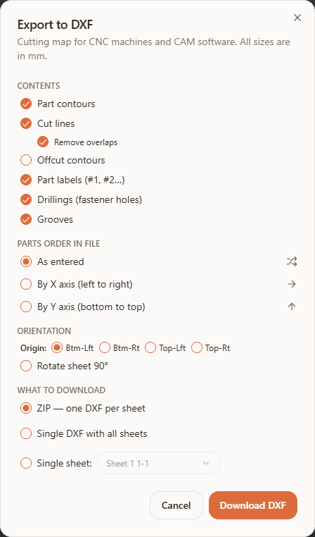
There is a fifth route with no files at all: a saved project can be shared by link. The recipient opens the cutting map in a browser in view mode and downloads whichever format they need. Every export option is covered in PDF / Excel / DXF export.
Three mistakes in a cutting map
- Dimensions given without edge banding. A part designed at 600 mm and banded with 2 mm on two sides becomes 604 mm in the assembly. Either subtract the banding up front or switch on automatic edge deduction on the Pro plan.
- The map sent without banding marks. The shop will cut the parts correctly but will not know which sides to band. Turn the Edges layer on before exporting.
- The kerf in the map does not match the saw. You calculate for 3 mm, the machine cuts wider, and the last part in the row falls short. Confirm the kerf before the calculation, not after the cut.
Build a cutting map from your own part list — calculation and PDF export are free.
Make a cutting mapIf you are comparing tools rather than preparing a specific order, see how an online service differs from desktop cutting software.
Frequently asked questions
What is a cutting map, in plain terms?
It is a diagram of a sheet showing how your parts will be arranged on it and which lines the saw will follow. The material is cut from it, and the finished order is checked against it.
Can I make a cutting map online for free?
Yes. Calculating the layout, viewing the map and exporting to PDF and Excel are all on the free plan. DXF export for CNC and label printing are Pro features.
Do I need dedicated cutting map software?
Not if the service runs in a browser — nothing needs installing and the project opens on any device. Desktop software is mainly for shops that build cutting into their production workflow.
Can a finished cutting map be edited manually?
Yes. In the editor a part can be dragged within the sheet, rotated 90°, or moved to another sheet or offcut through the buffer. The magnet helps snap it to neighbours and to the edge without leaving gaps.
Which format should go to the cutting shop?
PDF is enough for manual cutting, Excel suits record keeping, and a CNC machine needs DXF. You can also simply send a link to the saved project and let the recipient open the map in a browser.
Why did some parts not make it onto the map?
The "N of M placed" counter flags this immediately. The usual reason is a part that does not fit the sheet once edge margins and kerf are taken into account. Check its dimensions and the margin settings.
A good cutting map is one that raises no questions in the shop: dimensions, banding and cut order are all visible, and the remnants have been counted in advance. Everything else is optimisation detail — and you can keep reworking it right up until the sheet is cut.