
Fasteners and drilling
How automatic fastener selection between parts works, where to override it manually, and how to set a corner shape and drill holes in a part's detail view.
What this is
Fasteners are what hold parts together: confirmats, minifix connectors, hinges, screws and others. Raspili picks a suitable fastener on its own, based on how parts meet each other, and shows the result in the "Fasteners" section of the parameters panel. Drill holes are the actual holes for that hardware; you can view and add them manually in a part's "Detail" view, which is also where the corner shape is set.
When to use it
- To check which fastener Raspili picked for a joint between parts.
- To manually set a specific fastener type where auto-selection doesn't fit.
- To view and edit the exact drill holes for that hardware.
- To set a non-standard corner shape for a part — a notch or a radius.
Where it is
Select a part → the "Fasteners" section in the "Parameters" panel; exact holes — the "Detail" icon (magnifier) above the part
How to use it
It's in the "Parameters" panel, under "Edging".
Each side shows the picked fastener with a quantity (e.g. "Confirmat 7×50 — 3 pcs"), or "no neighbor" if there's no other part nearby.
Pick a specific fastener type instead of "Auto" — the list depends on which parts meet at that side.
The magnifier icon above the selected part in the scene (or the "Detail" button in planar mode).
The part's 4 corners appear: top-left, top-right, bottom-left, bottom-right.
"Notch" — set Leg X and Leg Y; "Radius" — set a single radius value. The part's schema updates instantly.
Only appears for corners with a notch or radius.
A new hole appears at the click point (or centered, if added via the button).
X and Y — position on the part, Ø — diameter, "Depth" — hole depth, "Through" — a hole that goes all the way through.
Only works for manual holes — auto-generated ones are view-only.
Select the hole by clicking it first.
Interface overview
The "Fasteners" section in the "Parameters" panel — one row per side of the part.
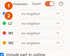
- 1"Count" — turns fastener calculation on or fully off for this part.
- 2L1, L2, W1, W2 — the fastener for each of the 4 sides. The value is "Auto" (Raspili picks it), a specific fastener type, or a "no neighbor" status if that side isn't adjacent to anything.
When "Auto" finds a neighboring part, it shows the picked fastener with a quantity instead of the status — for example, "Confirmat 7×50 — 3 pcs". The set of available types depends on which parts are joined: cabinet-to-cabinet usually gets a confirmat, minifix, rafix or corner bracket; a back panel gets a screw; a facade gets a hinge; a shelf gets a shelf support or a confirmat.
Part detail view
A large schema of the selected part with dimensions — opened with the magnifier icon above the part in the scene.

The header shows the part's name and size. On the right — a collapsed "Corner shape" and a "Holes (N)" counter with an "Add" button. While there are no holes yet, a short usage hint is shown instead.
"Corner shape" — the part's 4 corners, each independently set to square, notched or rounded.
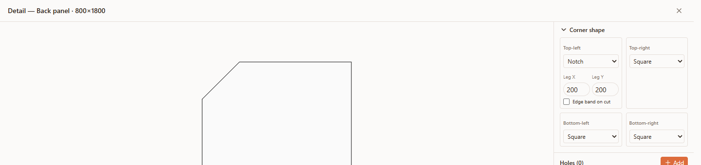
In the screenshot, the top-left corner is switched to "Notch" with 200×200 mm legs — the part's schema instantly shows the cut corner. For a "Radius" corner, a single radius value is set instead of two legs.
The hole list and the editor for the selected one sit below "Corner shape".
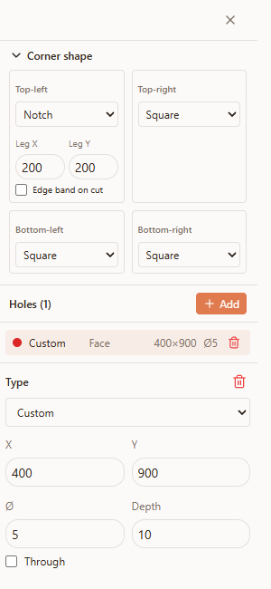
- 1A hole row — type, face, coordinates and diameter; the colored marker on the left shows whether it's auto-generated (gray, view-only) or manual (red, editable).
- 2The editor — appears below the list when a manual hole is selected: type, X/Y, diameter (Ø), depth, and a "Through" checkbox.
Possible errors
| What you see | Why it happens | How to fix it |
|---|---|---|
| A side shows "no neighbor" | There's no other part on that side to pick a fastener against | This isn't an error — the fastener appears on its own once a neighboring part is there. A manually picked type is kept and applied once the parts are joined. |
| "Corner cut exceeds allowed size" | The notch legs or the radius are larger than the part's dimensions allow | Reduce the Leg X/Y or radius value. |
| A hole won't drag | It's an auto-generated hole (gray) — view-only | Only manual holes (red) can be moved or deleted. |
| Fasteners aren't calculated at all | The "Count" switch in the "Fasteners" section is off | Turn "Count" on if this part actually needs fasteners. |
Tips
- Leave "Auto" wherever there's no special requirement — Raspili picks the right fastener for most standard joints on its own.
- Only override fasteners manually when you really need to — for example, when a project calls for a specific hardware type.
- Check corner shapes on the schema right away — "Exceeds allowed size" shows up immediately, before you even save.
- Don't try to edit auto-generated holes — if you need another hole nearby, add a separate manual one instead.
Frequently asked questions
How do I open a part's detail view?
Select the part and click the magnifier icon above it in the 3D scene, or the "Detail" button in planar (2D) mode.
What's the difference between auto-generated and manual holes?
Auto-generated holes (gray) are computed automatically from how parts connect and are view-only. Manual holes (red) are ones you add yourself — you can move and delete them.
Why doesn't the fastener match what I picked manually?
Check that the side is actually overridden (not "Auto"). If the issue persists after changing the type, it's worth checking with support.
Can all four corners of a part have a different shape?
Yes, each of the four corners — top-left, top-right, bottom-left, bottom-right — is set independently.
Where's the exact fastener article number set later on?
In the designer you set the type and position. The final spec is built automatically and carried over to cutting along with the project.