
Edging and drillings
How to assign edging to a part's side and mark drillings and grooves for hardware used during assembly.
What this page is
The "Edging" and "Drillings" steps of the cutting wizard, right after "Parts". "Edging" — which edging type to glue onto which side of each part. "Drillings" — fastener holes (hinges, confirmats, minifix, and others) and grooves for every part; some of them are transferred automatically from the 3D furniture designer, and the rest can be added and adjusted by hand.
When to use it
- To band the visible edges of parts and work out the edging length needed.
- To mark holes for hardware and grooves for a drilling machine or manual drilling.
- To check and, if needed, adjust drillings that were carried over automatically from the 3D designer.
Where it is
Cutting-project wizard → the "Edging" and "Drillings" steps (right after "Parts")
Default edging types and the "Drillings" step's on/off switch are set on the "Parameters" step — covered in the "Creating a cutting project" article. Entering sheets and parts is covered in "Sheets, parts, offcuts".
How to use it
Shows every part with four columns — L1, L2, W1, W2 (the long and short sides).
Only one type can be picked per side — checking a different type automatically clears the previous one.
The "Total edging length" cards add up the meters for each type separately, across every part quantity.
It's on by default; turning it off hides the "Drillings" step from the wizard, but the data itself isn't lost and comes back if you turn the switch on again. Covered in detail in "Creating a cutting project".
The row expands, revealing the part preview and the "Drillings" and "Grooves" tables.
A new drilling appears at the coordinates you clicked; X is measured from the left edge (length), Y from the bottom edge (width).
Adds a drilling with default values — coordinates and other settings can then be edited right in the table row.
Hinge cup, Confirmat (face), Confirmat (end), Shelf support, Minifix, Rafix, Dowel, or Custom.
Face, or one of the ends — L1, L2, W1, W2; for "Hinge cup", "Minifix", and "Rafix" the surface is locked to "Face" and can't be changed.
Depth can't exceed the part's thickness — Raspili automatically clamps whatever you enter.
The "Depth" field locks for that drilling — depth always equals the part's full thickness.
A new groove row appears with default values.
Side is L1, L2, W1, W2, or Face; on the part preview a groove shows as a blue strip along the chosen side.
Interface overview
The "Edging" step
Edging for every side of every part.
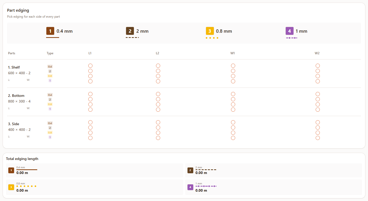
- 1Edging-type legend — a colored number and thickness for each type defined on the "Parameters" step.
- 2"Parts" table — every part with its size and quantity, and next to it, columns L1, L2, W1, W2 with a checkbox per edging type.
- 3"Total edging length" — the sum in meters for each edging type, across every part quantity, counting every side that uses that type.
The "Drillings" step — parts list
Each part is a collapsible row with badges showing the drilling and groove counts.

- 1Part name and size — "Length×Width×Thickness"; thickness comes from the sheet the part references.
- 2"Drillings: N" badge — how many fastener holes are already marked on the part; hidden if there are none.
- 3"Grooves: N" badge — how many grooves are marked on the part; hidden if there are none.
- 4Arrow on the left — expands and collapses the part; only one part can be expanded at a time.
An expanded part — preview and tables
Opens by clicking a part's row in the list.
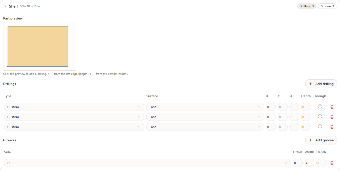
- 1"Part preview" — a scaled rectangle of the face; drillings show as rings (larger, Ø 12 mm and up) or dots (smaller) — hollow for through holes, filled for blind ones; edge drillings show as a tick mark near the nearest edge. Clicking the preview adds a drilling at that point.
- 2"Drillings" table — columns Type, Surface, X, Y, Ø, Depth, Through, a delete icon; the "Add drilling" button sits above it.
- 3"Grooves" table — columns Side, Offset, Width, Depth, a delete icon; the "Add groove" button sits above it.
Drilling types: "Hinge cup" (a hole for mounting a door hinge), "Confirmat (face)" and "Confirmat (end)" (a joint made with a confirmat screw from different sides), "Shelf support" (a hole for a shelf pin), "Minifix" and "Rafix" (eccentric connectors), "Dowel" (a hole for a wooden dowel), "Custom" — any hole not tied to a specific fastener type.
Possible errors
| What you see | Why it happens | How to fix it |
|---|---|---|
| The "Drillings" step says "No parts. Add parts in the 'Parts' step." | The project doesn't have any parts yet | Enter parts on the "Parts" step, then come back to drillings. |
| The "Drillings" step is missing from the wizard's step switcher | Drillings are turned off in the project settings | Turn on the "Drillings" switch on the "Parameters" step. |
| The depth you entered for a drilling or groove shrank automatically | Depth can't exceed the part's thickness — Raspili clamps the value | Expected behavior; if you need a different depth, check the thickness of the sheet the part references. |
| The "Depth" field is disabled for a drilling | That drilling has "Through" checked — a through hole always spans the full thickness | Uncheck "Through" if you need a limited depth instead. |
| The surface picker is empty or only shows "Face" | The chosen drilling type (Hinge cup, Minifix, Rafix) has the surface locked | Expected for these types; pick a different type if you need an edge drilling. |
| The calculation result disappeared after editing edging or a drilling | Expected behavior — changing a part's data clears the previous calculation | Go to the "Calculation" step and tap "Calculate" again. |
Tips
- Place drillings by clicking the preview, then fine-tune coordinates in the table — it's the fastest way to rough in a layout without losing precision where it matters.
- Double-check drillings carried over from the 3D designer before calculating — the automatic transfer saves time, but it's worth confirming the coordinates visually on the preview.
- Don't check "Through" for hardware that needs a limited depth — hinges and confirmats usually shouldn't go all the way through a part.
- Set up edging types once, on the "Parameters" step — then the "Edging" step is just a matter of checking boxes per side.
Frequently asked questions
Can different sides of the same part have different edging?
Yes — the L1, L2, W1, and W2 columns on the "Edging" step are set independently; each side can only have one edging type at a time.
How many edging types can I set?
2 on the free plan, up to 4 on Pro; the types themselves and their thickness are set on the "Parameters" step — covered in "Creating a cutting project".
Why is there a separate "Drillings" step if hardware is already set up in the 3D designer?
Drillings added in the 3D designer are carried over to cutting automatically, but it's worth checking and adjusting them here if needed — for example, if a part didn't come from the designer but was added directly in the cutting tool.
What's the fastest way to add a drilling?
Click the point you need on the part preview — a drilling appears right there with those coordinates; the type, diameter, and depth can be refined afterward in the table.
What does the "Through" checkbox mean?
The hole goes all the way through the part; for that drilling, depth isn't set and always equals the part's thickness.
Why can't I pick a surface for some drilling types?
"Hinge cup", "Minifix", and "Rafix" are only ever mounted on the face of a part by design — the surface choice is locked for them.
What if the "Drillings" step disappears from the wizard?
Check the "Drillings" switch on the "Parameters" step — if it's off, the step is hidden, but data entered earlier isn't deleted and comes back once you turn the switch on again.